Large Format Laser Cutting Machine Introduction
- By:Metmac
- 2023-03-07
- 216
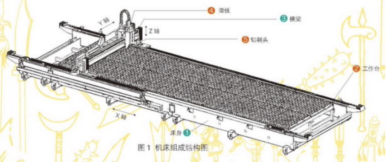
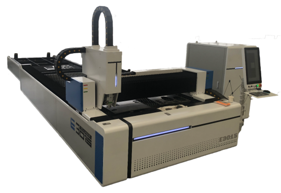
Large-format laser cutting machines are mainly used in ship processing, rail transit, construction machinery, mining machinery, 5G iron towers, pressure vessels and other industries. (Z-axis) composition, see Figure 1.
Figure 1
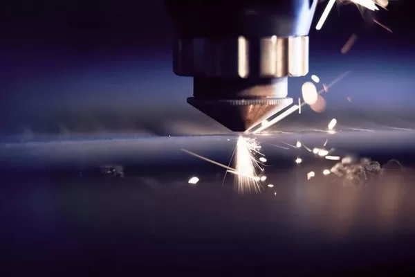
The machine tool adopts the gantry double-drive structure, the bed is welded as a whole, and the beam steel plate is bent and welded. In terms of technology, both rough machining after annealing and finishing after heat aging treatment. The bed is driven by rack and pinion, and the X-axis traveling mechanism is designed according to different guiding components to ensure the meshing backlash of the gear transmission. A workpiece is placed on the workbench, the beam moves in the X-axis on the bed, the cutting head moves in the Y-axis on the beam, and the distance between the cutting nozzle and the plate moves in the Z-axis up and down, and three CNC laser cutting machines are completed. direction of free movement. During processing, the laser light emitted from the laser is emitted from the cutting nozzle through the reflected light path, and focused on the inside of the plate to obtain a high power density, so that the material within the spot range reaches the melting or vaporization temperature in a short time.
The carbon steel plate is cut by the oxidation melting cutting method. The laser has no cutting force when processing thin plates, so the feed speed can be close to the fast feed speed of the machine. The X-axis stroke is determined by the length of the track, which is driven by a rack and pinion, and can be infinitely extended in units of 1m. In order to be smooth and smooth in gear transmission, it is necessary to ensure the clearance between the tooth surfaces during meshing. The backlash of the parallel gear pair can be adjusted by increasing or decreasing the center distance (radial clearance). The guide part of the machine tool is one of the important parts of the machine tool. It acts as a load bearing and guides the executive parts. It largely determines the rigidity and precision of the machine tool. The guide part of the X-axis can be used. Rolling guide rails or rails, different walking mechanisms are designed according to the selected guide components.
( Click Picture For More Details)
Calculation of Technical Parameters
- Other technical parameters: the load is the beam part + memory shaft part + cable drag chain, that is, 500+120+80=700kg; safety factor K=1.5~2: mechanical efficiency η=90%; linear guide rail friction coefficient μ=0.1; rail Friction coefficient u=0.2.
- Gear design Spur gear modulus m. ≥1.5mm, helical gear modulus mn≥2mm, number of teeth Z>17, choose spur gear with modulus m.=3mm, number of teeth Z-25, tooth width b=30mm, servo motor speed nmotor=3000r/min
- The calculation process of the transmission ratio of the reducer is as follows. Uniform force F1=Lmg=0.1×700×10=700N acceleration force F2=ma=700×5=3500N
- F together=F1+F2=4200N
- Single gear driving force F single=4200÷2=2100N
- Acceleration time t=v/(60×a)=80/(60×5)=0.27s
- Every time the servo motor rotates once, the moving distance of the moving part is L=πmZ/i=2.355×103mm
- Motor shaft inertia J=m(L2π)2+J1=56.23kgm2 gear torque T=F and r=157.5Nm
- Gear speed n gear=v×60×1000/(C2rr)=338rmin power P=T×n/9550=2.473kW
- Motor power Pelectricity=P×k/m=2.93 pieces of W, take 2.9kW reducer transmission ratio i=n machine m gear=8.8, take 10
- Design of rail-guided X-axis traveling mechanism
The walking rail is used for railways, and the cut surface is in the shape of “I”. The type and strength are expressed in kilograms per meter (kgm). The heavier the weight per meter, the greater the load that the rail can bear. The rail is composed of three parts: rail head, rail waist and rail bottom. It has the advantages of low price, good bending resistance and strong vibration resistance. The disadvantage is that the transmission accuracy is not high and the stability is poor.
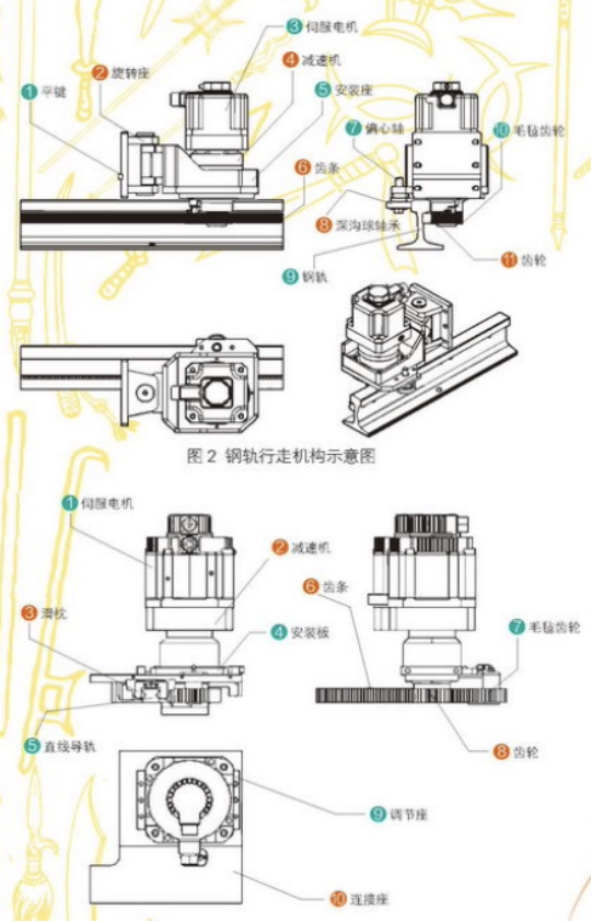
Figure 2
The rail running mechanism (Figure 2) adopts the rack and pinion driven by the servo motor reducer as the movement mode. The rack and pinion has a large transmission load, long fatigue life and stable and reliable operation. Through this transmission, the cutting head can be pushed smoothly to the cutting position quickly and accurately. In the traveling mechanism, the eccentric shaft bearing is used to clamp the rail, the felt gear is lubricated, and the rotating seat rotates to adjust the backlash. The flat key restricts the up and down displacement of the mechanism, and the cutting track runs smoothly. Linear guide rail guide X-axis walking mechanism design The linear guide rail relies on two rows of bearing balls at 45° to the two sides of the track as a guide, so that the steel balls in the slider do infinite rolling cycles on the surface of the guide rail.
The load platform can easily do high-precision linear motion along the slide rail. The advantages are sensitive movement, good low-speed stability, and high positioning accuracy. The disadvantages are poor rigidity and vibration resistance, high cost, and good maintenance measures.
The mechanism uses the mounting plate to process the straight slot and the flange mounting hole of the reducer, and the lubrication system uses felt gears for follow-up lubrication. The specific structure is shown in Figure 3. The mounting plate is connected to the connecting seat. The M10 socket head screw on the adjusting seat bears against the side of the mounting plate. Use a hexagonal wrench to turn the screw to adjust the lateral displacement of the gear and adjust the meshing backlash of the rack and pinion.
-
The Advantages of Using a Sheet Roll Forming Machine in Manufacturing
2024/09/14 -
How to Optimize Your Laser Sheet Cutting Machine for Maximum Performance
2024/09/12 -
How to Maximize Efficiency with Modern Sheet Metal Working Machines
2024/09/04 -
The Environmental Benefits of Using Duct Board Grooving Machines
2024/09/03
-
A Guide to the Latest Innovations in Sheet Metal Folding Machines
2024/11/29 -
Key Features to Consider When Investing in a Sheet Metal Folding Machine
2024/11/28 -
Enhancing Precision with Advanced Sheet Metal Folding Machines
2024/11/27 -
How to Choose the Right Sheet Metal Folding Machine for Your Workshop
2024/11/26
